Welcome to part 3, the final part of this series of tutorials, on building your own drink mixing robot. Hopefully by now you’ve built the robot and gotten a little bit familiar with the code. This part of the tutorial will go over the general operation of the robot, alternative designs, and parts of the code that are unfinished. If you are just joining us in this post, here is the video again to get an idea of what we’re discussing:
Part 3: Operation, Caveats, and Further Modifications (you are here)
Adding Ingredients
In order to add ingredients, you have to add pumps. The ingredients and pumps match in a left-to-right fashion (if you are looking at the machine straight-on). To get to the pump controls, use the PUMP button in the top-right of the UI.
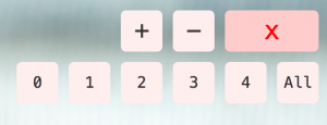
When the PUMP button is pressed, it opens up the pump controls, which look like this, minus the numbered buttons:
The (+) button will add a logical pump to the end of your list of current pumps, while the (-) button will remove a logical pump from the end of the list of pumps. You can add as many logical pumps as you want, but they will only work with the number of physical pumps that you have. Information on adding more physical pumps is in a section further down.
Numbered buttons in the pump controls correspond to the pumps on the machine. They allow you to activate an individual pump (or all pumps at once with the All button) for either debugging or cleaning purposes. Using the same control again will deactivate the pump.
Adding Drinks
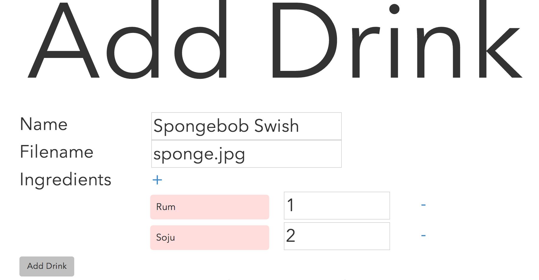
To add drinks, point your browser to http://localhost:3000/add after the app has been started up. You should see a page that looks like this:
The Name field corresponds to the name of the drink that will be displayed to the user. The filename field is the name of the image used. If no image is specified, a generic image will be used. Ingredients for the drink (an unlimited amount) can be added via the (+) button, and specific ingredients can be removed via the (-) button to the right of the ingredient.
Images are to be placed in the /public/images/drinks/ directory.
Drinks amounts are specified in a relative basis. This means if you have a drink with two ingredients (A and B), { A: 1, B: 2 } is the exact same as { A: 5, B: 10 }, which is the exact same as { A: 0.25, B: 0.5 }. This is because the software normalizes the amounts before calculating how much to be dispensed based on the desired size set by the user. There’s no need to worry about units of measure, just make sure the ratios are correct!
When you click the Add button, there is no confirmation that the drink is added; the form will be cleared. I have not added any code in for this yet, so if you would like to add it in, please send a pull request.
Editing Drinks
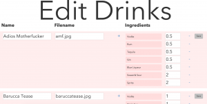
Drinks can be edited at http://localhost:3000/edit
You can edit drinks in this section. Click the Save button to the right of the drink that you want to edit after you are done editing. Again, there is no confirmation that it has been edited. Additionally, this page does not yet allow you to delete drinks or add/remove ingredients to a current drink. These have not yet been added, so if you would like to send a pull request for these, I would also appreciate it.
Further Modifications
If you’d like to increase the number of pumps that are supported, you’ll have to modify the code in two places (noted in teal below), both in the backend.js file:
public/javascripts/robot/backend.js
 pump0 = new five.Led(7);
 pump1 = new five.Led(6);
 pump2 = new five.Led(5);
 pump3 = new five.Led(4);
 pump4 = new five.Led(3);
// Add new pumps here
// You may want to change the pin numbers as well

...

exports.usePump = function (pump) {
 var using;
 switch(pump) {
  case 'pump0':
   using = pump0;
   break;
  case 'pump1':
   using = pump1;
   break;
  case 'pump2':
   using = pump2;
   break;
  case 'pump3':
   using = pump3;
   break;
  case 'pump4':
   using = pump4;
   break;
// Add new pump-strings here as 'pump5', 'pump6'...
  default:
   using = null;
   break;
 }
 return using;
}
Alternative Designs
There are a few alternative designs that you can use for this robot. Instead of using 5 transistors and 5 resistors, you can use a single ULN2803A darlington transistor array (thanks CaTiO). Also, instead of using a computer running node.js, you should be able to simplify the design to a Raspberry Pi. However, I have not had any experience with the Pi yet.
3d Printer
A word about the 3d printer I used. It is a Makerbot Replicator 2X and I have been very happy with it. I’m not sponsored by Makerbot at all, but I just think that the machine is splendid and has given me very little trouble (compared to the Printrbot Simple that I had before it–I guess you get what you pay for). I have enjoyed using it immensely. I print with ABS plastic from SainSmart and I find that it works pretty well. The issue that I have with it is that the spool does not fit the spool holders that come with the Replicator 2X, so I had to use a custom holder that was on Thingiverse.
Well, that’s all. Thanks for taking the time to read through my post. Hopefully you have learned something; I know I have definitely learned a lot in the process. If you have any questions or comments, don’t be afraid to add something to the discussion below. Thanks!
This is a continuation of the previous post where I went over how to print, wire, solder, and assemble the robot. With this post, I will be discussing the software design of the robot, as well as the considerations that I took in designing it. I’m assuming that you have some working knowledge of JavaScript and MongoDB. I realize that the Angular.js code that is written here may not be the most efficient, since the whole point of me building the robot was to learn Angular (and also make some thing awesome). Therefore, if you spot any changes that need to be made to the code to increase efficiency or whatnot, please let me know in the comments or send a pull request to the Bar Mixvah GitHub. Here’s a video of the robot in case you missed the previous post:
So, before I proceed, a few people have asked why we need so much technology to do something so simple as mixing drinks. What is the MEAN stack? It consists of MongoDB, Express.js, Angular.js, and Node.js. Everything works beautifully together because it’s all JavaScript (and MongoDB, which uses BSON, similar to JavaScript’s JSON). Why do we need the MEAN stack? Well, we don’t need it. But it makes things easier, so that’s why I’m using it.
MongoDB is used to store all of the drink and pump information
Express.js is the web server so that your WiFi connected devices can access the interface
Angular.js is used on the front end to filter drinks based on what ingredients have been selected
Node.js is used on the backend to communicate with the Arduino
Preparing Your Arduino
The Arduino Nano talks to the Johnny-Five node.js package via the Standard Firmata protocol. You will need to flash Standard Firmata onto your Arduino:
Plug in the Arduino to your USB port on your computer
Open the Arduino software
Go to File > Examples > Firmata > StandardFirmata
Click the Upload button in the top-left
Starting the App
Bar Mixvah requires node.js, MongoDB, and git. Follow the respective links to download and install them if you haven’t already. The commands here are run in the Mac OS or Linux shell; I don’t have much experience with the Windows command line, but I believe most of the stuff is the same (except you should remove sudo if you see it, and run your command prompt as an administrator). To start off, clone the Bar Mixvah GitHub repository onto your local hard drive:
git clone https://github.com/ytham/barmixvah.git
cd into the directory and install all node.js packages:
cd barmixvah
npm install
This will install all of the packages required for the node.js app to run. Before you can run it, you must start mongodb:
sudo mongod
In a new terminal window, cd to the barmixvah directory again. Plug in the Arduino to your computer via USB. You can now start the robot app:
node app.js
Congrats! It should now be up and running. You can now point your web browser to http://localhost:3000 to check it out. The rest of this post will go towards explaining the code for the robot. If you haven’t yet set up the Arduino, you can read the next section to set up the UI without having it connected to an Arduino for testing purposes.
Debugging the App Without the Arduino
The app can be started without an Arduino by commenting out the following section:
> public/javascripts/robot/backend.js
var board, pump0, pump1, pump2, pump3, pump4;
/*var five = require('johnny-five');board = new five.Board();board.on('ready', function () { // Counting down pins because that's the orientation // that my Arduino happens to be in pump0 = new five.Led(7); pump1 = new five.Led(6); pump2 = new five.Led(5); pump3 = new five.Led(4); pump4 = new five.Led(3); board.repl.inject({ p0: pump0, p1: pump1, p2: pump2, p3: pump3, p4: pump4 }); console.log("\033[31m[MSG] Bar Mixvah Ready\033[91m");});*/
This will prevent Johnny-Five from initializing the Arduino. This is useful for testing UI or backend code on the go if you’re not tethered to an Arduino.
General Flow
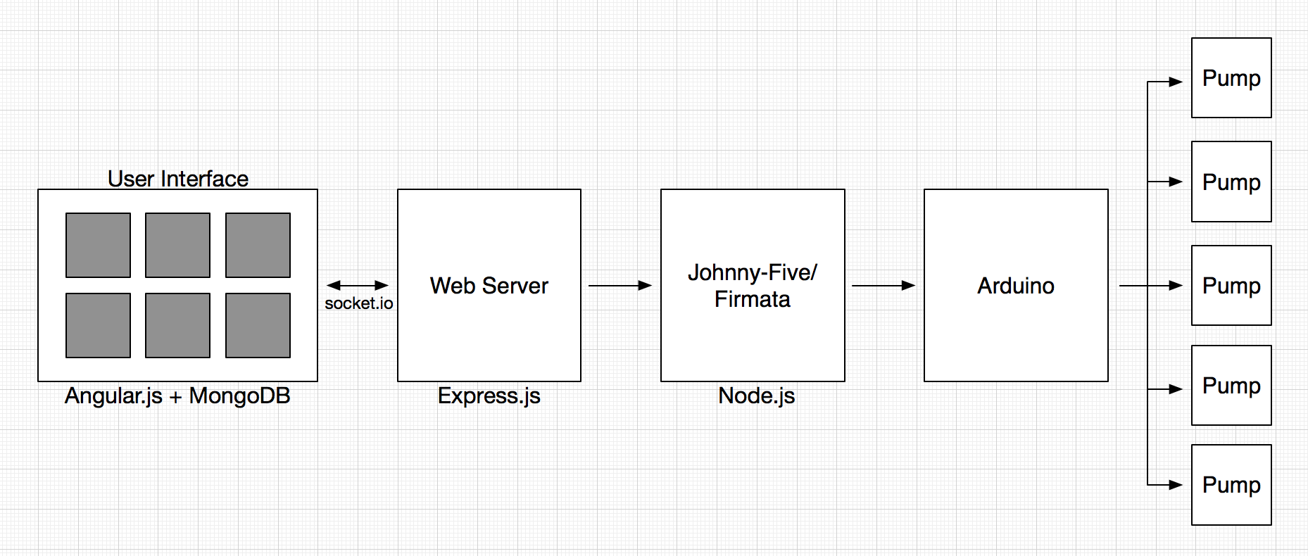
Here’s a pretty simplified design that gives you a general picture of how the code works with the physical elements:
When a user interacts with the UI, Angular.js (or some custom JavaScript/jQuery) will change what is displayed on the screen. If the user decides to make a drink with the Make button, the selected drink JS object and drink size are passed to the backend via socket.io. From there, the app passes the data to the Johnny-Five package and communicates when to start/stop the array of pumps.
Drink and Pump Schemas
The drink schema that will be saved into MongoDB (via the Mongoose node.js package) is specified below:
The drink objects have a name, image, and an array of ingredient objects that contain the their name and relative amount. Ingredient amounts are relative and unitless because then the user can specify the drink size and get the actual amount of each ingredient to pump based on the specified drink size.
We have one pump object that contains an array of pumps that have a label (such as “pump0”, “pump1”, etc…) and an ingredient associated with that pump. In this case, we use the label because order is important and we want to ensure that the pumps are in the correct order regardless of how they are modified. When any pump is updated via the UI, the entire pump object that contains all of the (up to five) pumps is updated in MongoDB. This keeps things consistent and ensures that pumps are updated correctly.
> routes/index.js
exports.updatePump = function (Pump) {
 return function (req, res) {
  Pump.findOneAndUpdate({ _id: req.body._id },
   {
    ingredients: req.body.ingredients
   },
  function (err, pump) {
   if (pump == null) {
    Pump.create(req.body);
    pump = req.body;
   }
   res.send(pump);
  });
 }
}
Choosing Pumps
The pump system is set up so that as soon as the any of the pump ingredients are changed, the entire pumps object (containing all of the individual pump ingredients) is changed. The ng-click directive in this case calls two functions. One function saves the pumps object by overriding the previous pumps object, the other figures out the number of duplicate ingredients and writes the number of duplicates that are checked at other times (such as when the Make button is pressed). The reason why we don’t just check pumps for duplicates immediately is if, say you are a user and you want to move “Orange Juice” from pump0 to pump2. You might change pump2 to “Orange Juice” first, but if that throws an error since “Orange Juice” is also currently on pump0, that is not a very good user experience.
> views/index.jade
div.pumpContainer(ng-repeat="pump in pumps.ingredients")
 select.mixers(ng-change="savePumpValue($index); writeNumDuplicates()", ng-model="pump.ingredient", ng-options="i for i in ingredientsList")
The savePumpValue function sends a post request with the $scope.pumps object. The pumps object is data bound to the view via Angular, so the changes in the dropdown are automatically modified on the front end, but we just need to save it into the database so that when the user refreshes the page, they get the same pumps instead of having to start over.
> public/javascripts/controller/DrinkController.js
$scope.savePumpValue = function (pumpNumber) {
 $http.post('/updatepump.json', $scope.pumps).success(function (data) {
  if (data) {
   console.log(data);
  }
 });
};
From here, the web server receives the HTTP POST request via the updatepump.json endpoint.
> app.js
var routes = require('./routes/index');
...
app.post('/updatepump.json', routes.updatePump(Pump));
And then the updatePump function is run, creating a pump if there is none, and updating the current pumps object if it already exists.
> routes/index.js
exports.updatePump = function (Pump) {
 return function (req, res) {
  Pump.findOneAndUpdate({ _id: req.body._id },
  {
   ingredients: req.body.ingredients
  },
  function (err, pump) {
   if (pump == null) {
    Pump.create(req.body);
    pump = req.body;
   }
  res.send(pump);
  });
 }
}
Pump Operation
The pumps are switched on/off by the 5V from the Arduino pins going to the each of the TIP120 transistors, which in turn switch the 12V for the individual pumps. Since the Johnny-Five package contains a simple interface for LEDs, I decided to use its switch on/off properties for switching the pumps because it’s just a simple digitalWrite(HIGH/LOW). Here’s the code for it:
> public/javascripts/robot/backend.js
 pump0 = new five.Led(7);
 pump1 = new five.Led(6);
 pump2 = new five.Led(5);
 pump3 = new five.Led(4);
 pump4 = new five.Led(3);
The pumpMilliseconds function is used to run a single pump for a number of milliseconds. The usePump function (not shown here) determines which pump to use based on the pump input string.
> public/javascripts/robot/backend.js
function pumpMilliseconds(pump, ms) {
 exports.startPump(pump);
  setTimeout(function () {
 exports.stopPump(pump);
 }, ms);
}

exports.startPump = function (pump) {
 console.log("\033[32m[PUMP] Starting " + pump + "\033[91m");
 var p = exports.usePump(pump);
 p.on();
}

exports.stopPump = function (pump) {
 console.log("\033[32m[PUMP] Stopping " + pump + "\033[91m");
 var p = exports.usePump(pump);
 p.off();
}
Making a Drink
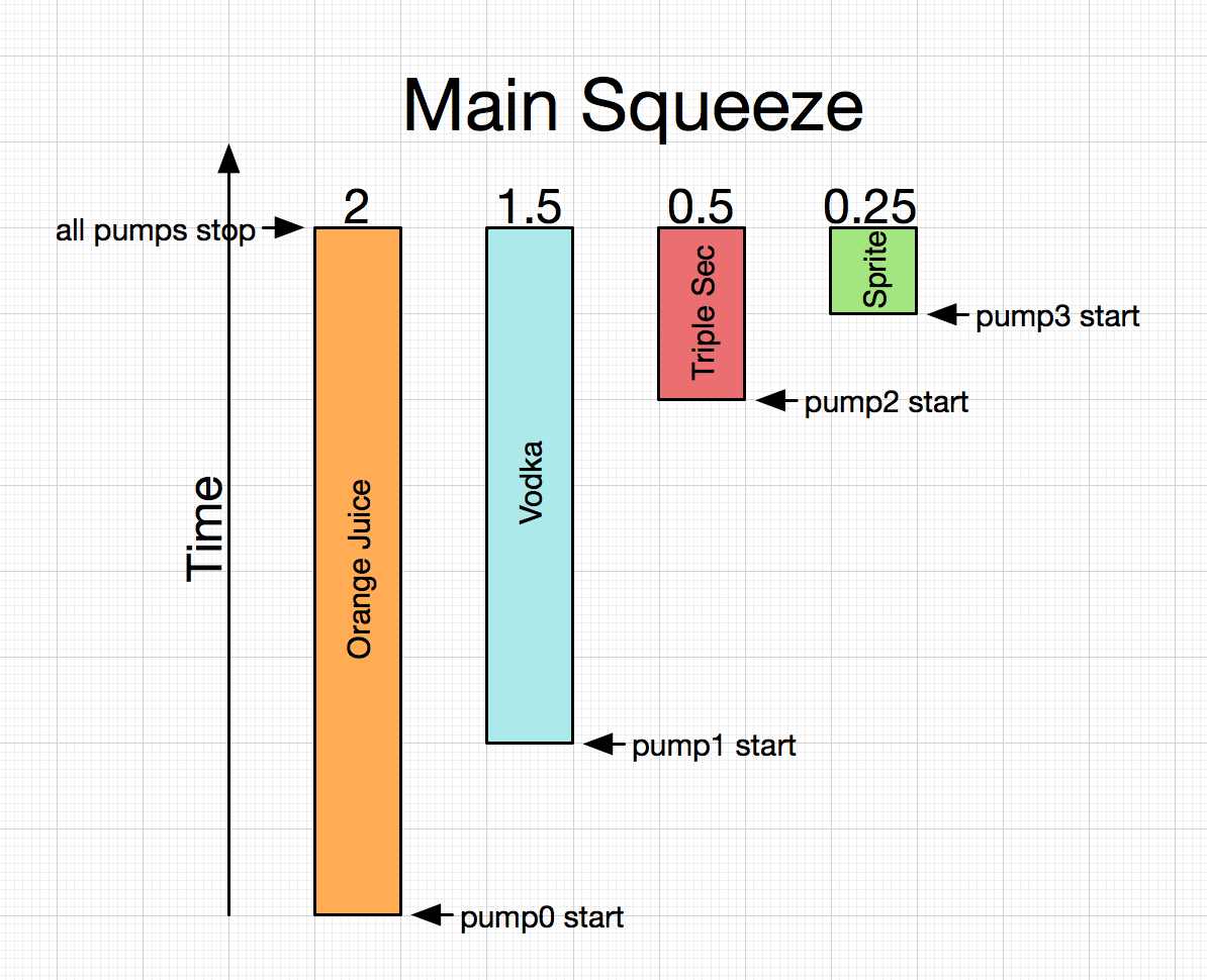
The simplicity of the UI hides much of the complexity behind the actual making of a drink. We want to make a drink that is top-biased in terms of ingredients. That is, all of the ingredients with smaller amounts should be on top so that gravity will cause them to mix into the drink. This adds a little bit of complexity in that we need to also pass a delay amount for each pump, but it is worth it for a drink that is mixed better! Here’s a diagram of how the pump timings will work out:
When the user picks a drink and size, the data is stored as a local variable in the Angular $scope.
The Angular ng-click directive in the jade template file specifies the function to be run in the Angular $scope when the div is clicked. In this case, when the div is clicked, the $scope.selectedDrink variable gets set to the current drink object. When the Make button is pressed, code on frontend.js does two things: 1) it does some visual trickery to turn the Make button into a progress bar, and 2) it does the calculations required to determine how long each of the pumps should fire for based on the ingredients in the drink and the size of the drink selected. So, here’s the code for what happens when we tap the Make button:
> public/javascripts/robot/frontend.js
$('#make').on('click touch', function () {
 if ($('#make').hasClass('noselection') === true) {
  alert('Please select a drink first.');
 return;
 }

 if ($('#make').hasClass('disabled') === true) {
  return;
 }
First, we double check to make sure that a drink has been selected first. We can’t make anything if there is no selected drink. Additionally, if the robot is already making a drink, the Make button will be disabled and should not make a drink until it is done with the drink it is already making. Next, in the following code, you’ll see how we do the visual progress bar for the Make button. We add the ‘disabled’ class to prevent additional drinks from being made until the current one is done, show the hidden #makeProgress div, and then animate it via its margin-left style. At the end of the animation, the anonymous callback function hides the makeProgress bar and removes the ‘disabled’ class. The whole thing is wrapped around a 200ms delay in order for us to get the $scope.pumpTime, which is calculated in the makeDrink function that is explained further down in this section. After this, we call the makeDrink function with the drink’s ingredients, the pumps, and the selected drink size ($scope.drinkTime).
The code below goes through getting the total amount of all of the ingredients, finding the ingredient with the largest amount, and also appending pump labels to the ingredients as a string so that we will be able to determine which pump to use after this data is sent to the backend.
> public/javascripts/robot/frontend.js
function makeDrink(ingredients, pumps, drinkSize) {
 // Check that there are no duplicate pumps ingredients
 if ($scope.pumpDuplicates > 0) {
  alert("Pump values must be unique");
  return;
 }

 // Get largest amount and index of that ingredient
 var largestAmount = 0;
 var amountTotal = 0;
 var largestIndex = 0;
 for (var i in ingredients) {
  amountTotal += Number(ingredients[i].amount);
  if (Number(ingredients[i].amount) > largestAmount) {
   largestAmount = ingredients[i].amount;
   largestIndex = i;
  }

  // Append pump numbers to the ingredients
  for (var j in pumps.ingredients) {
   if (ingredients[i].name === pumps.ingredients[j].ingredient) {
    ingredients[i].pump = pumps.ingredients[j].label;
    continue;
   }
  }
 }
After all of this, in the code below, you will see that we get the normalization factor, which is the drinkSize divided by the total amount of all drinks. With this normalization factor, we can multiply the largest amount of drink by this value in order to get the total pump time (since pumps will be running in parallel, the total pump time is the pump time of the ingredient with the highest amount). If you recall from above, this is the $scope.pumpTime that we delayed 200ms to get on the front end. After this, we modify the amounts all of the ingredients in the array based on the normalization factor, and add the delay so that we can top-weight the ingredients in the drink. At the end, we use socket.io to pass the ingredients object to the backend.
> public/javascripts/robot/frontend.js (continuation of makeDrink function)
 // Normalize
 var normFactor = drinkSize/amountTotal;

 var totalPumpMilliseconds = parseInt(normFactor * largestAmount);
 $scope.pumpTime = totalPumpMilliseconds;

 // Set the normalized amount and delay for each ingredient
 ingredients[largestIndex].amount = parseInt(normFactor * Number(ingredients[largestIndex].amount));
 ingredients[largestIndex].delay = 0;
 for (var i in ingredients) {
  if (i === largestIndex) continue;
  ingredients[i].amount = parseInt(normFactor * Number(ingredients[i].amount));
  ingredients[i].delay = ingredients[largestIndex].amount - ingredients[i].amount;
 }

 socket.emit("Make Drink", ingredients);
}
At the backend, app.js catches the “Make Drink” event from the frontend and passes it to the robot portion that handles the actual pumping.
> app.js
var robot = require('./public/javascripts/robot/backend.js');
...
io.sockets.on('connection', function (socket) {
 socket.on("Make Drink", function (ingredients) {
  robot.pump(ingredients);
 });
> public/javascripts/robot/backend.js
exports.pump = function (ingredients) {
 for (var i in ingredients) {
  (function (i) {
   setTimeout(function () { // Delay implemented to have a top-biased mix
    pumpMilliseconds(ingredients[i].pump, ingredients[i].amount);
   }, ingredients[i].delay);
  })(i);
 }
};
And that’s all there is to it!
Well, those are the main points that I wanted to highlight about the software design of the robot. If you have any questions or comments, post them in the comments section below and I’ll try my best to answer them. And, of course, don’t forget to follow me on Twitter: @yujiangtham.
I built a robot that mixes drinks named Bar Mixvah. It utilizes an Arduino microcontroller switching a series of pumps via transistors on the physical layer, and the MEAN stack (MongoDB, Express.js, Angular.js, Node.js) and jQuery for the frontend and backend. In this post, I’ll teach you how I made it. You can follow along and build one just like it! I’ve also put the 3d model (blender), stl files, and the code up on GitHub for you guys to download. See the link at the bottom of the page. Here’s the video of the robot:
Navigation:
Part 1: Hardware and Electrical Design (you are here)
First, a little bit more about the robot. The entire thing costs approximately $180 to make. All of the parts are 3d printed, so you’ll need a 3d printer to build this. I used the MakerBot Replicator 2X, but any 3d printer should do. Total time to print the pieces is about 18 hours, depending on your settings, and assembly wiring, and Here’s a list of parts that need to be purchased:
Other tools required for the job are: a hacksaw to cut two of the 12″ rods in half, a wire stripper, soldering iron, and solder to connect the wire to the pin connectors and coaxial power connector, and a multimeter to check your work.
For the first part of this tutorial, I’ll focus on the 3d model, printing, and assembling the physical robot. The second part of the tutorial deals with the code, and the third part will deal with the operation of the robot.
Design
Bar Mixvah is designed to use a system of 5 peristaltic pumps that are switched by 5 bipolar junction transistors (TIP120), all controlled by an Arduino, which itself is controlled by the Johnny-Five package on the node.js/express web server that is running on your laptop/windows tablet (or maybe Raspberry Pi? I haven’t tried). Having it on a web server allows users to order from any device, be it a phone, tablet, or other laptop that can connect to your WiFi access point’s internal network. Practicality-wise, maybe it’s not necessary. However, in my experience, people seem to enjoy ordering from a tablet that they’re holding in their hands more than a stationary screen attached to the robot.
The physical design of Bar Mixvah around the usage of 5/16″x12″ steel rods. I chose this length and size because they’re sturdy, readily available at your local hardware store, and not too big or small. They’re also relatively cheap at ~$2-3 per piece, depending on where you buy from. The problem with 3d printing is that it’s goddamn slow. If you want to build a medium sized robot like this one, it would take days to print all of the necessary parts. In fact, you don’t even need to print these parts; you could fasten them together using plenty of other methods. However, I don’t have access to a metal shop, am a terrible welder, and wanted a friendly looking robot, so I chose this combination of 3d printing the joints and connecting them via metal shafts.
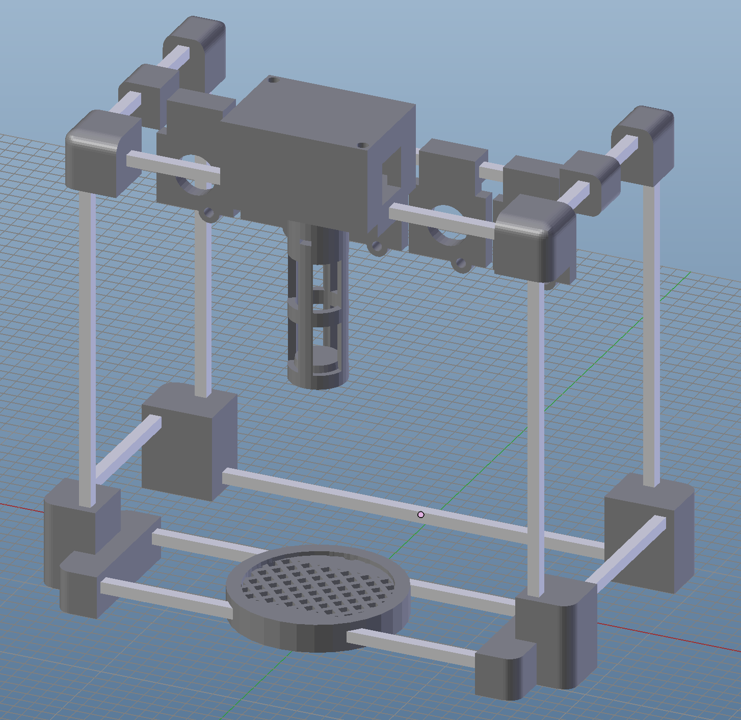
Here’s a screenshot of the 3d model, which, fortunately, looks exactly like the real thing after I finished building it. Ah, the miracles of science!
Printing the Parts
The stl files can mostly be printed in the orientation that they are in, however two files should be rotated 180 degrees on the x-axis so that they can be printed without major supports. These two pieces are Center – Board Cover – Top.stl and Center – Common Drink Channel.stl. Additionally, Center – Pump Holder.stl should be printed flat by rotating it 90 degrees so that no support pieces are needed. You will need to turn on printing with supports to ensure that the holes where we will be inserting the 5/16″ steel rods are printed to the right size.
One more thing that has been brought to my attention: the .stl files are may be 10x smaller than they should be in your 3d printing software. If that’s the case, you will need to scale up the objects 10x in all dimensions. It seems to happen regardless of the 3d software that I use when I convert to .stl. No idea why.
The Peristaltic Pumps
What is a peristaltic pump? If the word sounds familiar to you, it’s because you most likely heard of peristalsis in one of your biology classes at some point in time. Peristalsis is the system that your body uses to swallow food. Your throat muscles contract and relax in a way to create a waveform that pushes food in your throat down into your stomach. Peristaltic pumps work on the same principle, albeit with a slightly different execution. The clear plastic tube extends through the pump, and rollers propelled by a DC motor create a waveform that pushes liquid through the tube. Peristaltic pumps are safe and hygienic because liquid never actually contacts any part of the pump; only the plastic tubing is ever in contact with the liquid.
The peristaltic pumps come with some very short plastic tubing. This is obviously inadequate for our current application, so we’ll have to replace the plastic tubing. This requires us to take apart the pump. Fortunately, this is not a hard thing. Instead of trying to explain it, you can view the following video to figure out how it is done.
Soldering
Before connecting any wires, you’ll want to do all of the soldering. You’ll have to solder the 5.5mm x 2.1mm coaxial power connector to two jumper wires, one for the positive lead and one for the negative lead. Plug in your 12V DC power supply to the wall, then plug the coaxial power connector into the DC power supply. Use your multimeter to find out which lead is positive and negative by placing the probes on two of the leads until you find that the multimeter says 12V; those are you positive and negative leads (if it says -12V, then you’ve got the positive and negative leads switched). Unplug the coaxial power connector. Strip two wires and solder one to each of the coaxial power connector’s leads. After you’re done soldering, wrap any exposed metal around the leads in electrical tape.
Next, you’ll want to solder wires to the leads of the peristaltic pumps. The positive lead of the pump should be labeled, so you should not need to guess. If it is not labeled, you will just need to make note of which way the pump is turning and make sure that all of them are turning in the same direction. Don’t worry about the polarity of the leads on the pump breaking anything, since connecting them backwards will just make the pump go in the opposite direction. However, I want to emphasize that you’ll probably want to ensure all of the pumps are pumping clockwise (if they are facing you; you can see through the tiny circle in the middle which direction they are pumping when turned on). After this is done, once again wrap the leads in electrical tape.
Wiring
Here’s where it gets a little bit tricky. The actual wiring is not too complicated, but it requires a little bit of finesse due to the confines of space that we are working with. Since we are fitting everything on a single breadboard, we need to ensure everything is placed in the right spot.
In case you haven’t used a breadboard in a while, each of the numbers running down the breadboard indicate an individual node. The center divides the two sides, so they are separate nodes. The (+) rail running up the left and right side of the breadboard is one node per side, and it is the same with the (-) rail.
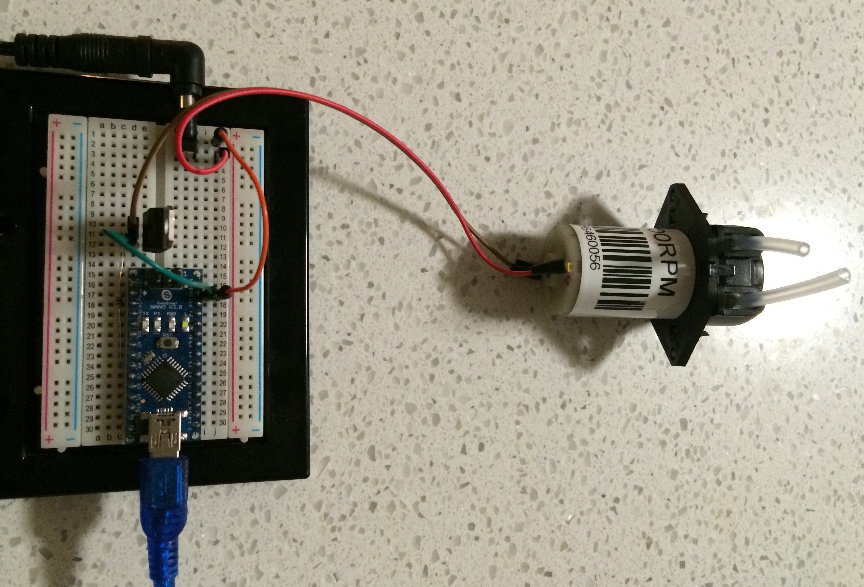
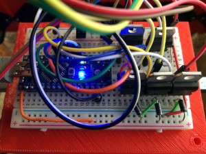
The first thing that you should do before getting any wiring done is to hook up your pumps individually and ensure they are all working. The photo below shows a little bit more complex of a circuit. To check if it’s working, you can just connect the coaxial power connector and pump on a breadboard and plug in the power and ensure that the pump works.
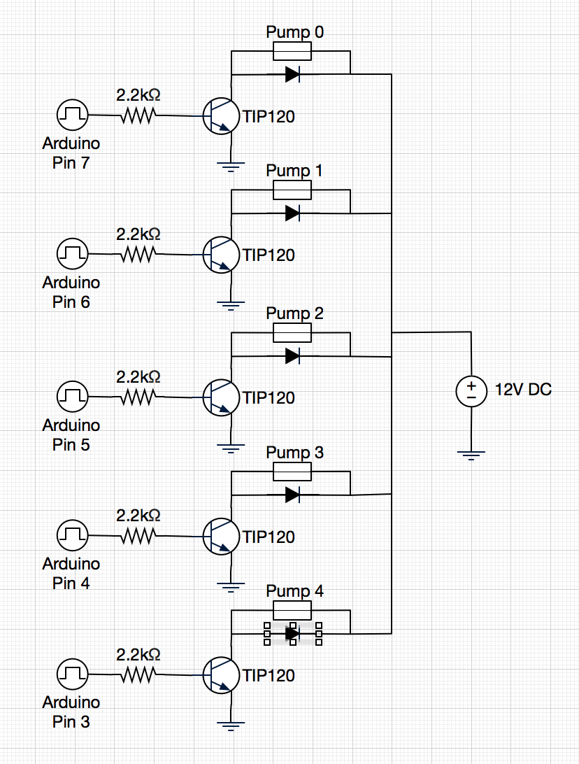
Here’s the wiring diagram for the robot. As you can see, it’s relatively simple:
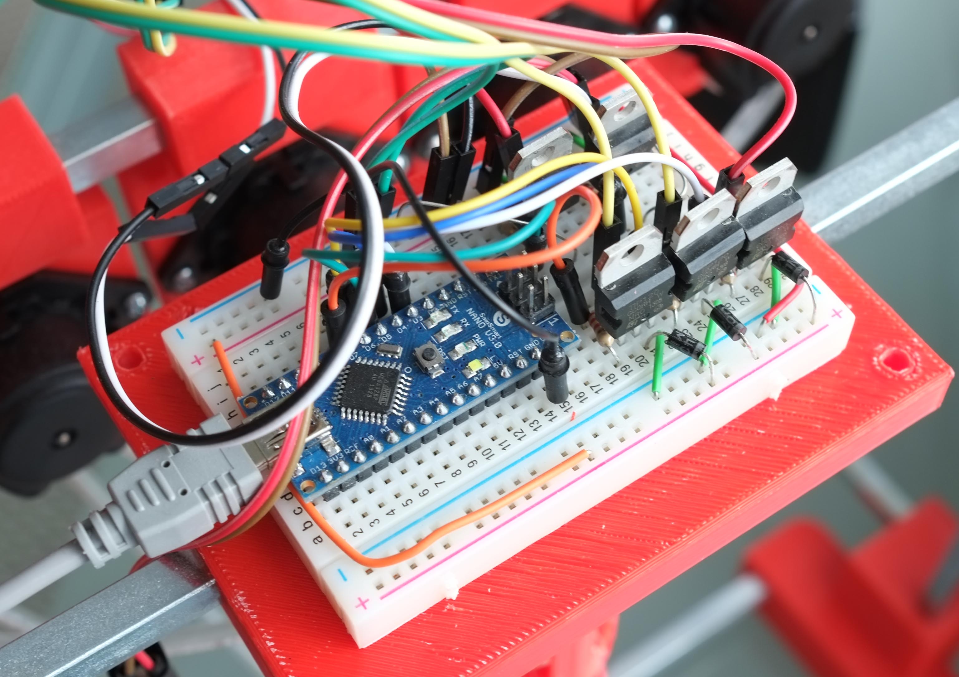
The tough part is that there is not much space, so you may need to have a set of needle-nosed pliers ready to put some of the things in. I recommend adding everything except transistors in first. Here’s how my breadboard looked like after I finished wiring it up:
Obviously, yours may look slightly different. However, I recommend placing the Arduino’s nano so that its USB port is on the edge of either side of the breadboard.
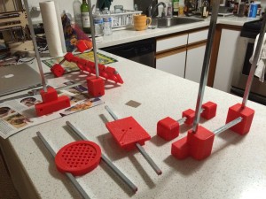
Assembly
After printing all of the pieces, remember which piece is which based on the 3d model. Remove all of the support pieces from the 3d printed items with pliers and/or a flathead screwdriver. It is likely that it will be a very tight fit for the steel rods, so you’ll need to push the rods in with a lot of force. I recommend using gloves.
Also, the order in which you assemble the robot IS important. Here’s the order that I used to assemble. Basically, you need to remember to assemble the middle parts first before connecting the left and right sides to them.
Insert all 5 of the pump holders onto one of the steel rods
Insert the drink tray into the center of two of the steel rods
Insert the breadboard holder (bottom piece) into the center of one steel rod
Assemble the left side, then assemble the right side
Insert the steel rods for the drink tray, pump holders, and breadboard holder into the left side
Connect all of the parts of the right side
Insert each of the pumps into a pump holder and screw them in with two #4 screws each
Attach the center channel to the top center section using two #6 screws
Tape the breadboard to the center of the top-middle section, ensuring that the top piece of this section will fit over it
Wire everything up based on the circuit schematic
Place the top piece (labeled #BarMixvah in the photo below) over the breadboard, moving wires around until everything fits snugly inside
Insert two #6 screws through the screw hole and tighten the nuts at the bottom to secure it in place
Well, that’s all for this week. Let me know if you have any questions in the comments and I’ll try my best to answer them.
I’ve never really sang in front of such a large audience before, so I was scared as hell, but I knew that the most effective way to get the message across about Strumbot would be to do a live demo. So, I decided that this was my chance and that I’d go for it. Anyway, the mic unfortunately didn’t really pick up the strumming, so it was mostly just karaoke, but I still had fun and definitely conquered another fear!
A little bit more about Strumbot: It’s a node.js application that is connected to an Arduino that powers a single servo. There is a web frontend using websockets that allows you to click different buttons to select different strum patterns. The servo I used is actually a complete piece of junk, but I unfortunately had nothing else. I actually have 2 high-speed servos coming in the mail, so they should be more up to the task. I had to sand down the pick to about 1/2 of its thickness because the servo was so damn weak! Strumbot is great for: people who want to learn gutiar, people who have no rhythm, and people who may have lost an arm but still want to play guitar. Strumbot is hosted on github here (and hardware, you’ll have to build yourself, obviously):
We won the 2013 OutsideLands Hackathon with our idea, OutsideLOAF (LOst And Found)! It was a pleasure working with my friends Andy Jiang and Jennifer Yip on this one! Basically, the app allows us to push realtime updates via SMS to people who have lost items. They can send something like “lost wallet” to the phone number we have set up, and when someone returns a wallet to the lost & found, they will push an SMS to the subscribers. Check out our video for more details:
Really awesome stuff. Hopefully it can help people find their lost stuff! 🙂
A few days ago I wrote part 1 of this tutorial on building a robotic arm that you can control with your hand movements in air. That tutorial dealt with the hardware side, so now I’ll talk about the software and how it all works together. In case you missed the first part, here’s the robot arm again:
Software
I used node.js with the leapjs and johnny-five packages to get data from the Leap Motion device and send it to the Arduino. The code itself is on GitHub here:
To run it, we’ll start by including the leapjs and johnny-five packages. You should install the packages first into the directory that you’ve unzipped everything to (npm install johnny-five && npm install leapjs). Next, in your Arduino software, you will need to go to hook up your board and then go to Files > Examples > Firmata > StandardFirmata (this is required for johnny-five). Then hit Upload.
To start the software:
node robotarm.js
The javascript library for Leap, called leapjs, works by waiting for a Leap ‘frame’ to be emitted to the listener, which then calls an anonymous function. We use this function to set our variables for later use with johnny-five. Here’s the basic form of it:
var controller = new Leap.Controller();
controller.on('frame', function(frame) {
  <get our Leap Motion data here>
});
The johnny-five package basically requires you to initialize a board and whatever else you are going to use inside that.
board = new five.Board();
board.on('ready', function() {
  servoBase = new five.Servo(3);
  servoShoulder = new five.Servo(9);
  servoElbow = new five.Servo(10);
  servoClaw = new five.Servo(6);
...
There are four servos in the arm, and three separate main controls. The base rotation is controlled by the x position of the hand. The end effector is controlled by the distance between two fingers. Finally, the shoulder and elbow joint angles are calculated by the inverse kinematics equation with inputs of the y and z coordinates.
function calculateBaseAngle(x) {
  var n = 100*normalize;
  x = 1.5+2*x/n;
  var angle = 90+Math.cos(x)*90;
  return angle;
}
While the Leap Motion device measures coordinates linearly, the base rotation is circular. I wanted to feed the x value through a cosine function so that it would not be too sensitive in midranged values. In order to calculate the base angle, I needed to get its range of values that would jibe well with a cosine function, and since the Leap Motion’s vales are in the range of -300 to 300 in Leap Space, I divided by 100 times the normalize value, which I will go into more detail in later paragraphs.
Since the servo rotation values are between 0 and 180, I wanted 90 to be the value when the arm was pointing forward, so modified the values so that they will range from 0 to 180 with 90 being in the center.
For the shoulder and elbow joint angles, the servos are placed in such a way as to allow for a large range of motion and “negative” values for the elbow. See the diagram below; the triangles show the pivot points of the servos.
In order to calculate the servo angles, we use an inverse kinematics equation. In physics, forward kinematics is used to calculate the position of an end effector, given its joint angles. However, with the Leap Motion device, we want to translate our hand’s position information into joint angles, thus we have to use inverse kinematics:
function calculateInverseKinematics(x,y,z) {
  z = -z;
  var t1 = Math.acos((square(z)+square(y)-square(l1)-square(l2))/(2*l1*l2));
  var t2 = Math.asin(((l1+l2*Math.cos(t1))*y-l2*Math.sin(t1)*z)/(square(l1)+square(l2)+2*l1*l2*Math.cos(t1)));
  return {
    theta1: t1,
    theta2: t2
  }
}
I invert the z value so that reaching towards the Leap Motion device in front of me will make the arm go forward as intended. The other theta1 and theta2 equations are simply the inverse kinematics equations from the following website:
The one thing to note is that we have to calculate the length (variables l1 and l2) based on the distance in terms of the Leap Motion device coordinates. The easiest way to find the length is to output your hand’s y-position to the console.
Place your arm section over the Leap Motion device and place your hand at the bottom of the section. Make note of the y-coordinate. Move your hand to the top of the arm section and make a note of the y-coordinate. Subtract the two numbers and the absolute value is the length in Leap space, which is what you will use for your length in the inverse kinematics equation. Do the same for the second arm section. These values will obviously be different for different arm lengths, so be sure to change this:
var l1 = 40*normalize;
var l2 = 40*normalize;
The normalize value is set to 3 in my app, but you can tweak it to change the sensitivity of the system as well as the range of motion. Normalize is also used in the input for the inverse kinematics function:
Since we are operating the shoulder and elbow joints on only the yz plane, we feed a zero into the x position (the x axis is calculated separately by the base rotation angle). I decreased the y input by 10 so that my hand would not have to be as high above the Leap Motion device, but you can play with this value and your mileage may vary. Another thing to note is that the elbow has an offset of 45 degrees. This is intentional so as to allow for “negative” elbow values.
The last part that needed to be done was to calculate the angle of the end effector, which would basically open and close the end effector (gripper). This was simply done in the Leap loop while calculating the finger distance:
What I’m doing here is basically getting the first two fingers (and ignoring the rest) and finding the distance in free space between them using a distance function which I have defined (which would be the same as any other distance function). The Leap motion does have one annoying bug, which is that it will no longer detect your two fingers if you put them together. Thus, I wanted to make the claw close without having to have my two fingers touch, which is the minimumClawDistance.
All of the global variables are read by the Johnny-Five board loop and the output is sent to the servos here:
The main things to note are the if statements; they basically protect the system from some unintended values (and will protect your arm from crashing down into the table if it his a NaN value). The loop reads values every 40ms, but you can play around with this value if you’d like.
Well, that’s all for now. I hope you enjoyed this post! Let me know if you have any questions.
This past week, I made a robotic arm that tracks your hand in free space using a Leap Motion, Arduino, and node.js. It tracks my hand very well. It is able to pick up stuff and set it down with relatively good precision, although there is definitely some room for improvement. I can’t pick up anything too heavy with it (mainly due to the gripper limitations), but it’s a good first try. See the video below:
I’ve spit this tutorial into two parts. This part 1 (you are here) deals with building the hardware. Part 2 deals with the software implementation. Let’s get started!
Hardware
I built all of this in the kitchen of my studio apartment in San Francisco. Unfortunately, I did not have access to any sort of workshop, so I had to use whatever I had lying around. I ended up ordering a few things from Amazon. The tools I used are as follows:
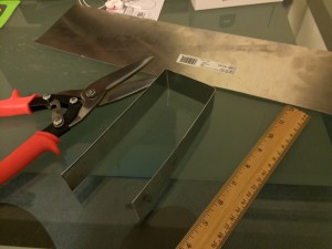
I bought a sheet of aluminum (0.025″ thick) and used the ruler and sharpie to figure out the dimensions of the arm. I then set about cutting the aluminum with the aluminum scissors (be sure to use gloves and eye protection since the aluminum is sharp). After the cut, The aluminum can be bent by hand, since it’s relatively thin. Push any corners that aren’t straight against your table to flatten them. We want to get the piece as flat as possible.
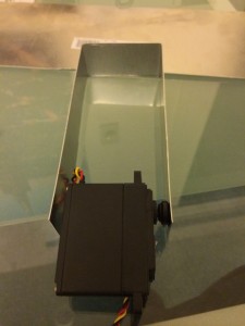
After that, we want to bend the piece of aluminum so that we can have some semblance of an arm section. We’ll bend the piece twice to get that in place. To make a sharper bend, use the ruler. Press the aluminum against the table and pull it up against the edge of the ruler.
Align the servo arm holes to the metal and mark the spots where you want to drill holes for the servo arm screw to attach to the aluminum arm section. Drill holes there.
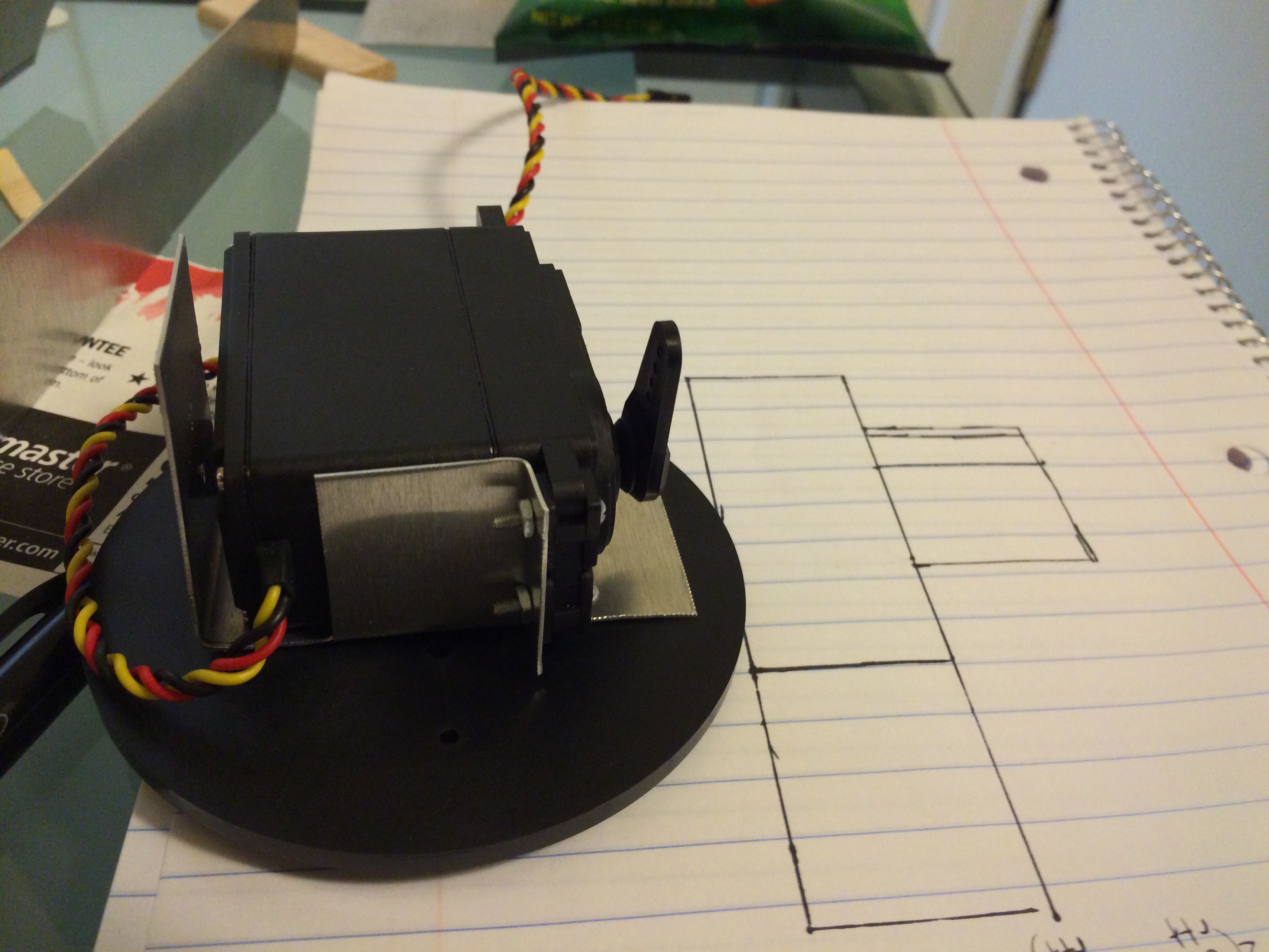
Before coming up with a design for the servo base attachment plate, you need to see what your servo’s range of motion is. We want to make sure that at the 90 degree point, the servo arm points up. The design I came up with is sketched on this piece of paper:
After that, creating the next arm section is similar, except we want to make it shorter and thinner for two reasons. One, less weight. Two, the end effector (gripper) will have some length as well, and we don’t want to have an out-of-proportion arm. That would look ugly.
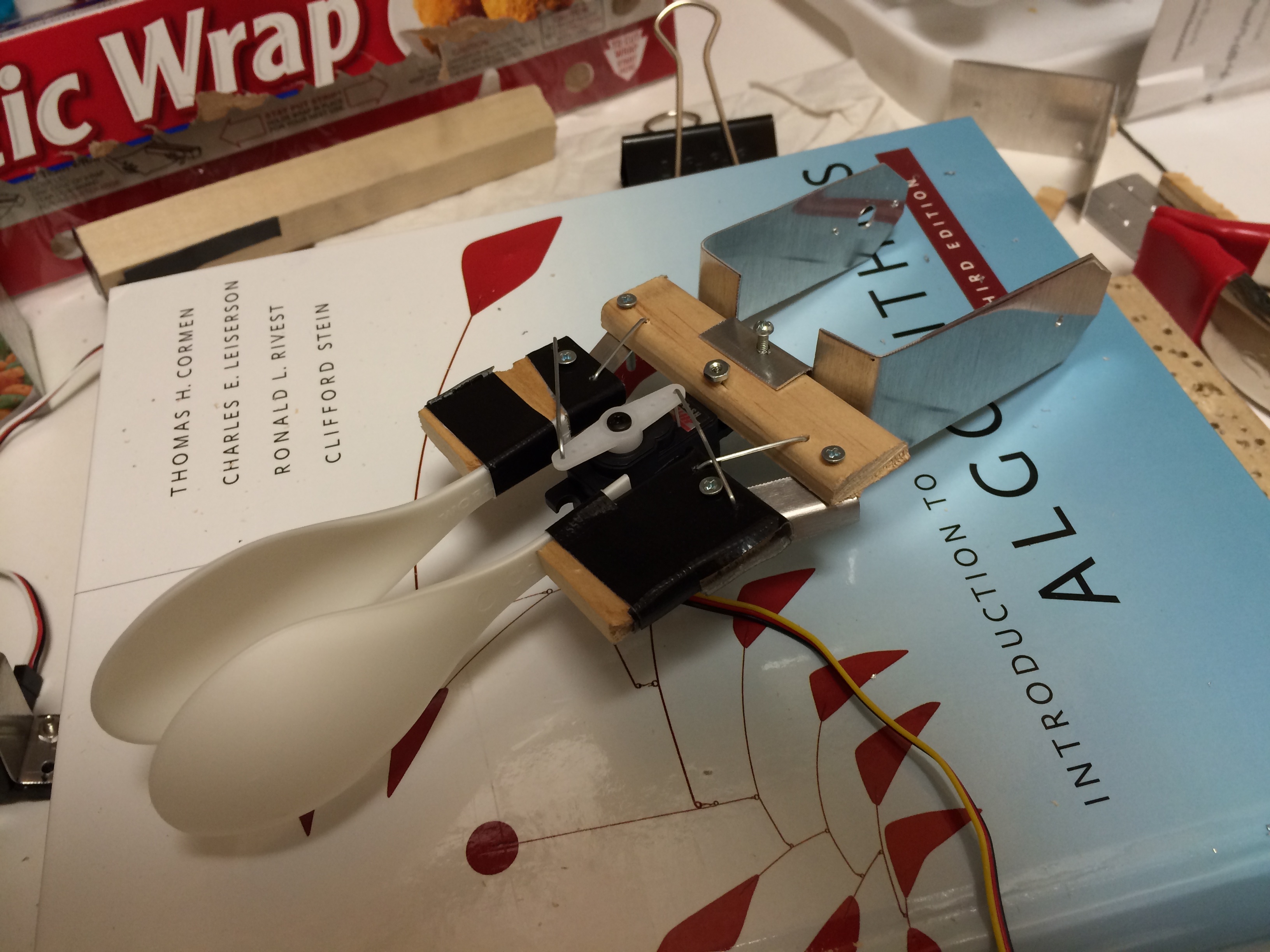
The end effector is a relatively simple design that mimics the following design I saw on youtube, except I used aluminum for the joints and paperclips to keep everything in place. Here’s the youtube video:
I tried using wood, but the pieces were too thin and I split them when I drilled the holes. Here’s the final end effector that I came up with. I used plastic spoons because I didn’t have anything else lying around. Here’s what it looks like after I put it together.
And then the rest of the arm just comes together after some additional drilling of holes and aligning of pieces! Here’s the final arm (minus the wood board that I used to attach to the base).
That’s that for the hardware! Continue to part 2 where I will go into detail about the software and how to link it to your Leap Motion device.