This past week, I made a robotic arm that tracks your hand in free space using a Leap Motion, Arduino, and node.js. It tracks my hand very well. It is able to pick up stuff and set it down with relatively good precision, although there is definitely some room for improvement. I can’t pick up anything too heavy with it (mainly due to the gripper limitations), but it’s a good first try. See the video below:
I’ve spit this tutorial into two parts. This part 1 (you are here) deals with building the hardware. Part 2 deals with the software implementation. Let’s get started!
Hardware
I built all of this in the kitchen of my studio apartment in San Francisco. Unfortunately, I did not have access to any sort of workshop, so I had to use whatever I had lying around. I ended up ordering a few things from Amazon. The tools I used are as follows:
- Aluminum Scissors
- Drill Set
- Clamp
- Ruler
- Sharpie
Additionally, the materials/components I had to buy to get this thing working are:
- Arduino
- HiTec HS-422 Servo
- HiTec HS-755HB Servo
- HiTec HS-81 Servo
- Radioshack “Standard Servo” or HiTec HS-311 Standard Servo
- Screws: #2×3/8″ screws (with nuts) for most things, and one #8 screw for the opposite-the-arm side of the big servo
- Aluminum sheet. 6″x18″x0.025″
- Wood
- Lynxmotion rotating base
- Leap Motion device
I bought a sheet of aluminum (0.025″ thick) and used the ruler and sharpie to figure out the dimensions of the arm. I then set about cutting the aluminum with the aluminum scissors (be sure to use gloves and eye protection since the aluminum is sharp). After the cut, The aluminum can be bent by hand, since it’s relatively thin. Push any corners that aren’t straight against your table to flatten them. We want to get the piece as flat as possible.
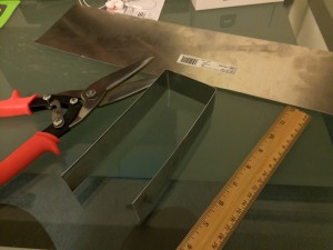
After that, we want to bend the piece of aluminum so that we can have some semblance of an arm section. We’ll bend the piece twice to get that in place. To make a sharper bend, use the ruler. Press the aluminum against the table and pull it up against the edge of the ruler.
Align the servo arm holes to the metal and mark the spots where you want to drill holes for the servo arm screw to attach to the aluminum arm section. Drill holes there.
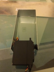
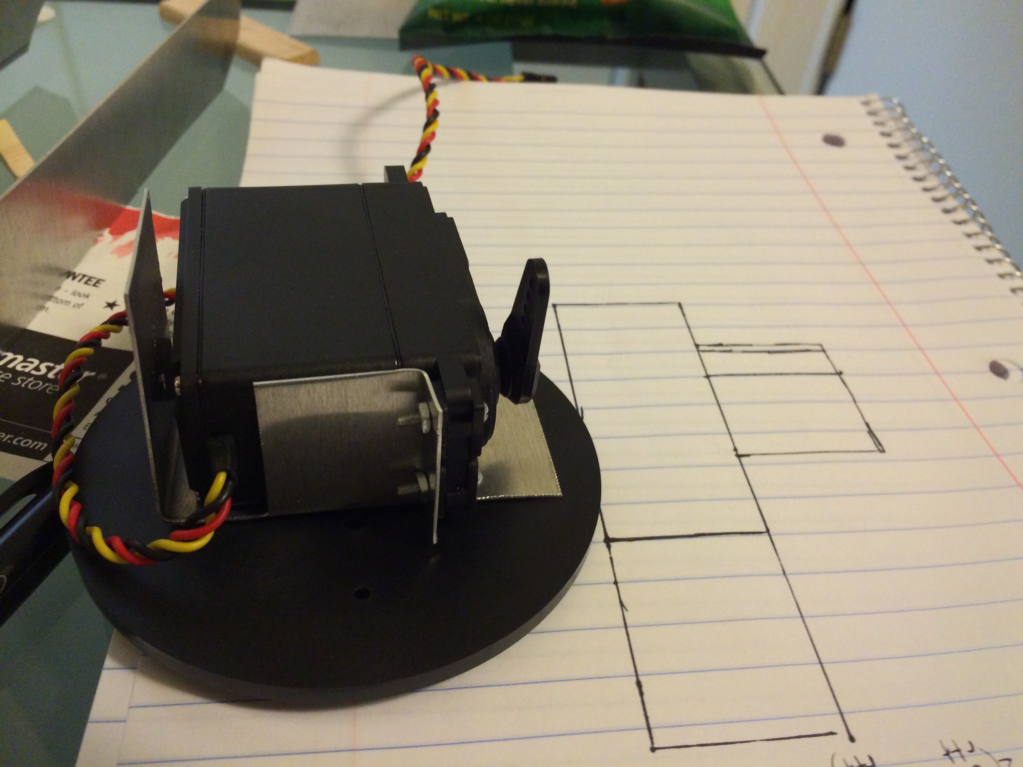
Before coming up with a design for the servo base attachment plate, you need to see what your servo’s range of motion is. We want to make sure that at the 90 degree point, the servo arm points up. The design I came up with is sketched on this piece of paper:
After that, creating the next arm section is similar, except we want to make it shorter and thinner for two reasons. One, less weight. Two, the end effector (gripper) will have some length as well, and we don’t want to have an out-of-proportion arm. That would look ugly.
The end effector is a relatively simple design that mimics the following design I saw on youtube, except I used aluminum for the joints and paperclips to keep everything in place. Here’s the youtube video:
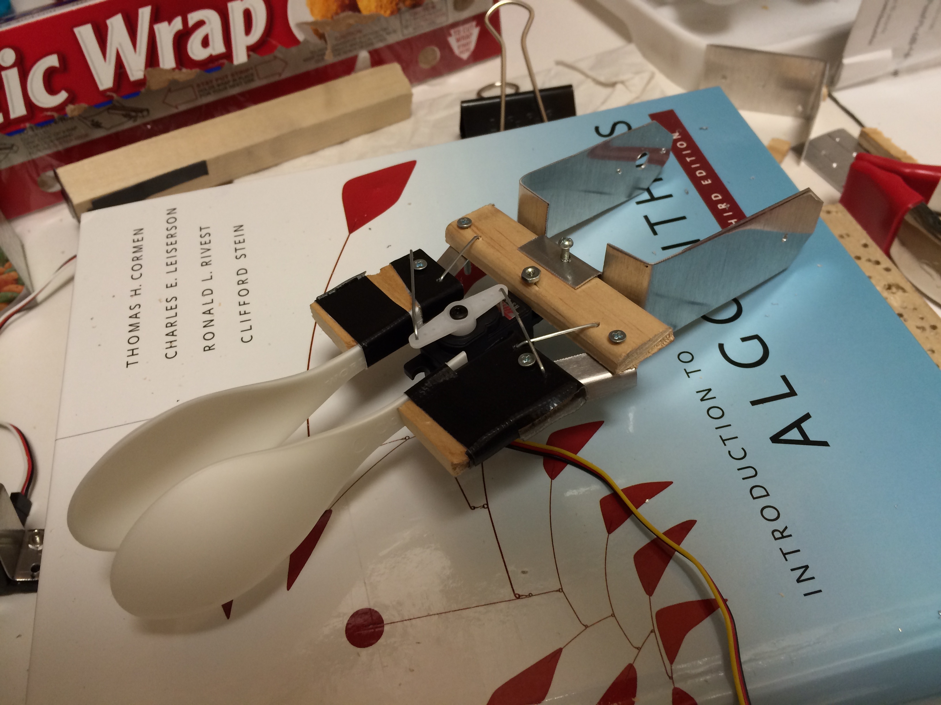
I tried using wood, but the pieces were too thin and I split them when I drilled the holes. Here’s the final end effector that I came up with. I used plastic spoons because I didn’t have anything else lying around. Here’s what it looks like after I put it together.
And then the rest of the arm just comes together after some additional drilling of holes and aligning of pieces! Here’s the final arm (minus the wood board that I used to attach to the base).

That’s that for the hardware! Continue to part 2 where I will go into detail about the software and how to link it to your Leap Motion device.