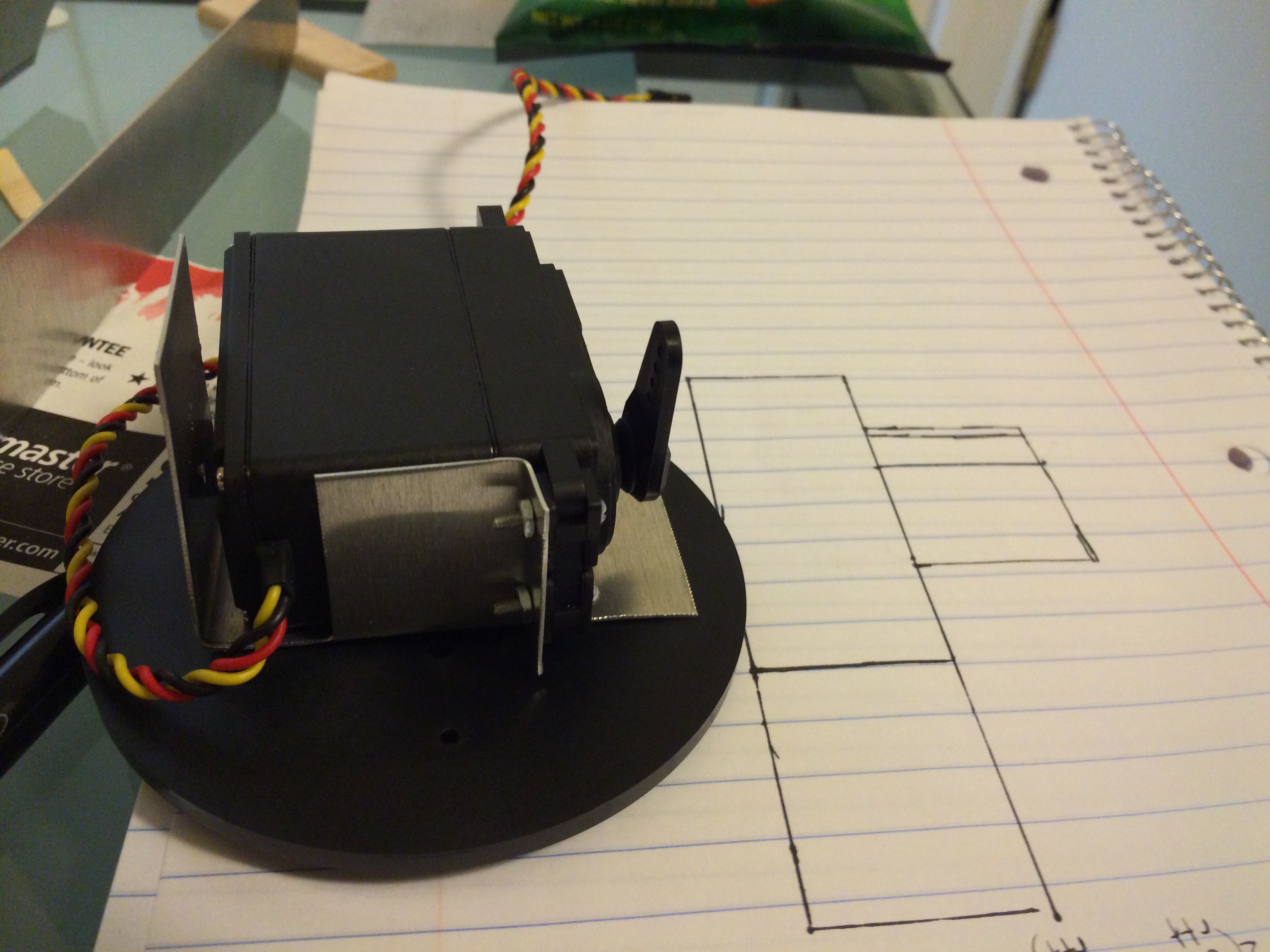
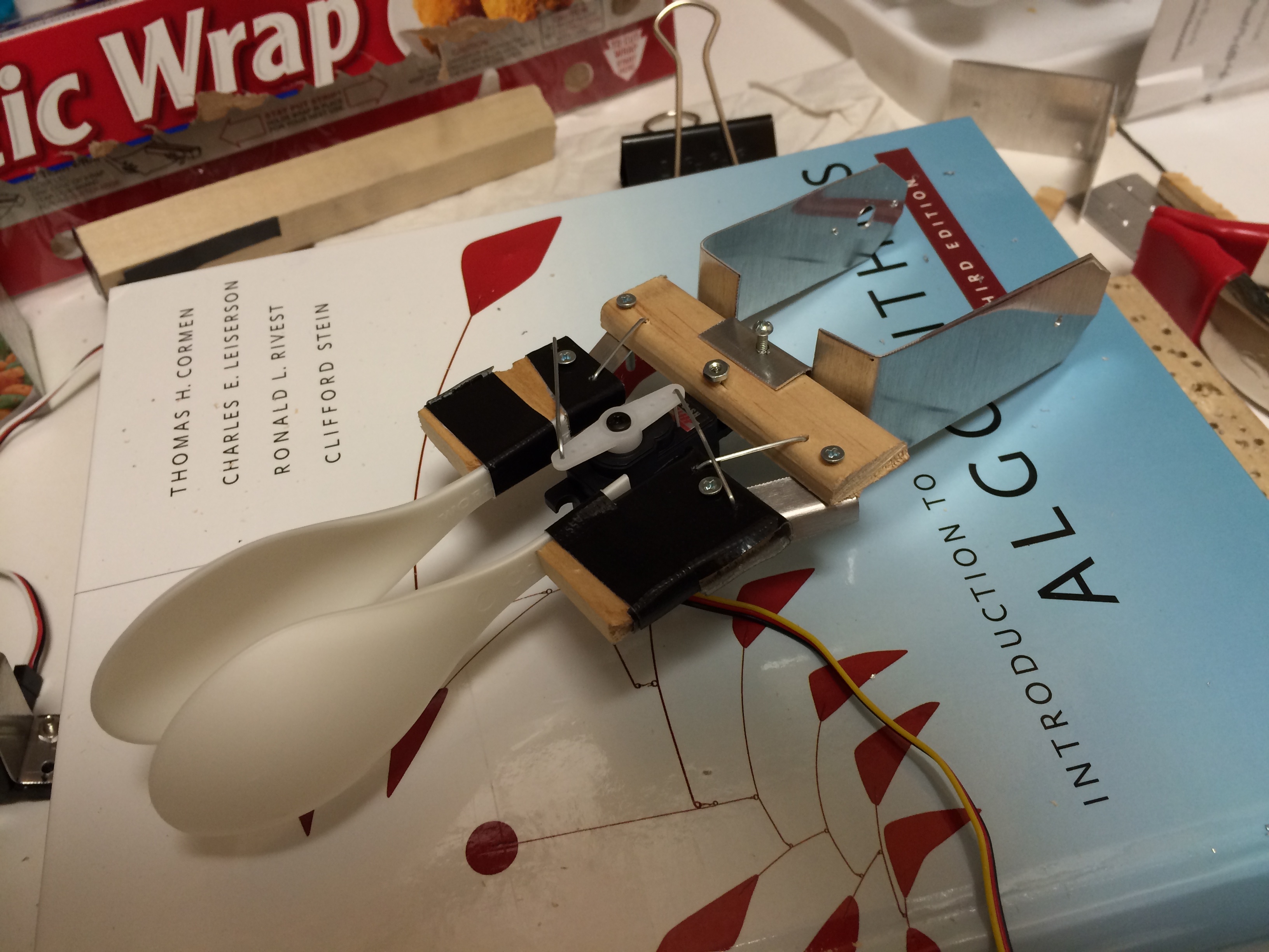
A few days ago I wrote part 1 of this tutorial on building a robotic arm that you can control with your hand movements in air. That tutorial dealt with the hardware side, so now I’ll talk about the software and how it all works together. In case you missed the first part, here’s the robot arm again:
Software
I used node.js with the leapjs and johnny-five packages to get data from the Leap Motion device and send it to the Arduino. The code itself is on GitHub here:
https://github.com/ytham/robotarm
To run it, we’ll start by including the leapjs and johnny-five packages. You should install the packages first into the directory that you’ve unzipped everything to (npm install johnny-five && npm install leapjs). Next, in your Arduino software, you will need to go to hook up your board and then go to Files > Examples > Firmata > StandardFirmata (this is required for johnny-five). Then hit Upload.

To start the software:
node robotarm.js
The javascript library for Leap, called leapjs, works by waiting for a Leap ‘frame’ to be emitted to the listener, which then calls an anonymous function. We use this function to set our variables for later use with johnny-five. Here’s the basic form of it:
var controller = new Leap.Controller();
controller.on('frame', function(frame) {
  <get our Leap Motion data here>
});
The johnny-five package basically requires you to initialize a board and whatever else you are going to use inside that.
board = new five.Board();
board.on('ready', function() {
  servoBase = new five.Servo(3);
  servoShoulder = new five.Servo(9);
  servoElbow = new five.Servo(10);
  servoClaw = new five.Servo(6);
...
There are four servos in the arm, and three separate main controls. The base rotation is controlled by the x position of the hand. The end effector is controlled by the distance between two fingers. Finally, the shoulder and elbow joint angles are calculated by the inverse kinematics equation with inputs of the y and z coordinates.
function calculateBaseAngle(x) {
  var n = 100*normalize;
  x = 1.5+2*x/n;
  var angle = 90+Math.cos(x)*90;
  return angle;
}
While the Leap Motion device measures coordinates linearly, the base rotation is circular. I wanted to feed the x value through a cosine function so that it would not be too sensitive in midranged values. In order to calculate the base angle, I needed to get its range of values that would jibe well with a cosine function, and since the Leap Motion’s vales are in the range of -300 to 300 in Leap Space, I divided by 100 times the normalize value, which I will go into more detail in later paragraphs.
Since the servo rotation values are between 0 and 180, I wanted 90 to be the value when the arm was pointing forward, so modified the values so that they will range from 0 to 180 with 90 being in the center.
For the shoulder and elbow joint angles, the servos are placed in such a way as to allow for a large range of motion and “negative” values for the elbow. See the diagram below; the triangles show the pivot points of the servos.

In order to calculate the servo angles, we use an inverse kinematics equation. In physics, forward kinematics is used to calculate the position of an end effector, given its joint angles. However, with the Leap Motion device, we want to translate our hand’s position information into joint angles, thus we have to use inverse kinematics:
function calculateInverseKinematics(x,y,z) {
  z = -z;
  var t1 = Math.acos((square(z)+square(y)-square(l1)-square(l2))/(2*l1*l2));
  var t2 = Math.asin(((l1+l2*Math.cos(t1))*y-l2*Math.sin(t1)*z)/(square(l1)+square(l2)+2*l1*l2*Math.cos(t1)));
  return {
    theta1: t1,
    theta2: t2
  }
}
I invert the z value so that reaching towards the Leap Motion device in front of me will make the arm go forward as intended. The other theta1 and theta2 equations are simply the inverse kinematics equations from the following website:
http://cnx.org/content/m11613/latest/
The one thing to note is that we have to calculate the length (variables l1 and l2) based on the distance in terms of the Leap Motion device coordinates. The easiest way to find the length is to output your hand’s y-position to the console.
Place your arm section over the Leap Motion device and place your hand at the bottom of the section. Make note of the y-coordinate. Move your hand to the top of the arm section and make a note of the y-coordinate. Subtract the two numbers and the absolute value is the length in Leap space, which is what you will use for your length in the inverse kinematics equation. Do the same for the second arm section. These values will obviously be different for different arm lengths, so be sure to change this:
var l1 = 40*normalize;
var l2 = 40*normalize;
The normalize value is set to 3 in my app, but you can tweak it to change the sensitivity of the system as well as the range of motion. Normalize is also used in the input for the inverse kinematics function:
if(frame.hands.length > 0) {
  handPosition = frame.hands[0].palmPosition;
  angles = calculateInverseKinematics(0,-10+handPosition[1]/normalize,handPosition[2]/normalize);
  moveBase = 180-calculateBaseAngle(handPosition[0]/2);
  moveShoulder = toDegrees(angles.theta1);
  moveElbow = 45+toDegrees(angles.theta2);
}
Since we are operating the shoulder and elbow joints on only the yz plane, we feed a zero into the x position (the x axis is calculated separately by the base rotation angle). I decreased the y input by 10 so that my hand would not have to be as high above the Leap Motion device, but you can play with this value and your mileage may vary. Another thing to note is that the elbow has an offset of 45 degrees. This is intentional so as to allow for “negative” elbow values.
The last part that needed to be done was to calculate the angle of the end effector, which would basically open and close the end effector (gripper). This was simply done in the Leap loop while calculating the finger distance:
if(frame.pointables.length > 1) {
  f1 = frame.pointables[0];
  f2 = frame.pointables[1];
  fingerDistance = distance(f1.tipPosition[0],f1.tipPosition[1],f1.tipPosition[2],f2.tipPosition[0],f2.tipPosition[1],f2.tipPosition[2]);
  moveClaw = (fingerDistance/1.5) - minimumClawDistance;
}
What I’m doing here is basically getting the first two fingers (and ignoring the rest) and finding the distance in free space between them using a distance function which I have defined (which would be the same as any other distance function). The Leap motion does have one annoying bug, which is that it will no longer detect your two fingers if you put them together. Thus, I wanted to make the claw close without having to have my two fingers touch, which is the minimumClawDistance.
All of the global variables are read by the Johnny-Five board loop and the output is sent to the servos here:
this.loop(40, function() {
  if(!isNaN(moveShoulder) && !isNaN(moveElbow)) {
    servoBase.move(moveBase);
    servoShoulder.move(moveShoulder);
    servoElbow.move(moveElbow);
  }
  if(moveClaw >= 0 && moveClaw <= 100) {
    servoClaw.move(moveClaw);
  }
  console.log("Base: " + Math.floor(moveBase) + "\tShoulder: " + Math.floor(moveShoulder) + "\tElbow: " + Math.floor(moveElbow) + "\tClaw: " + Math.floor(moveClaw));
});
The main things to note are the if statements; they basically protect the system from some unintended values (and will protect your arm from crashing down into the table if it his a NaN value). The loop reads values every 40ms, but you can play around with this value if you’d like.
Well, that’s all for now. I hope you enjoyed this post! Let me know if you have any questions.